Research Article | | Peer-Reviewed

Dynamic Analysis of the Influence of Railway Vehicle Speed on Passenger Ride Comfort When Wheels Undergo Polygonization Defects

Received: 24 January 2025     Accepted: 11 February 2025     Published: 7 March 2025
Views:       Downloads:
Abstract

The railway transportation system is currently undergoing a significant expansion. As a result, train lines are upgraded, and the technical condition of the rail vehicles that use them is also taken into consideration. However, under certain circumstances, wheels on rail vehicles may sustain damage while in use. Then, depending on the kind and degree of flaws, the profile of the wheels is no longer circular but rather changes. The quality of a passenger's ride comfort is diminished when a rail vehicle with a damaged wheel is in operation. The research considered one type of railway wheel untrueness wheel polygonization and focused on the evaluation of ride comfort for passengers based on results obtained from numerical and dynamic analyses. Simulations and calculations were carried out in numerical and dynamic multibody software. The results show that with increasing vehicle speed, the ride index also increases, which means that at high speeds, the ride comfort will be diminished. Furthermore, it found that the orders of wheel polygonization have an effect on ride comfort. With the increasing order of polygonization, the ride index also increases. According to the findings, this study has a significant impact on the maintenance planning for wheels and rails as well as operation management.

Published in International Journal of Mechanical Engineering and Applications (Volume 13, Issue 2)
DOI 10.11648/j.ijmea.20251302.11
Page(s) 53-62
Creative Commons

This is an Open Access article, distributed under the terms of the Creative Commons Attribution 4.0 International License (http://creativecommons.org/licenses/by/4.0/), which permits unrestricted use, distribution and reproduction in any medium or format, provided the original work is properly cited.

Copyright

Copyright © The Author(s), 2025. Published by Science Publishing Group

Keywords

Rail Vehicle, Ride Comfort, Flexible Wheelsets, Wheel Polygonization, Dynamic Simulations

1. Introduction
The railway industry is a significant component of the national economy. Due to the advantages of environmental protection, convenience, speed and safety, more and more passengers choose to travel long distances by train . Therefore, it must offer a high comfort level for passengers and crew. However, the comfort that passengers experience is usually perceived differently from one individual to another. A low vibration level is one of the important factors of a good ride comfort. The vibrations are mainly caused by track irregularities, from which they are transmitted via the bogies and the car body to the passengers . The carbody is not rigid, but bends and twists from the excitation coming from the bogies. In some circumstances, the structural flexibility of the car body accounts for half of the vibrations that are felt, with the remaining vibrations coming from rigid body motions. The problem of vehicle vibration is significant in the design and development of competitive cars given the present trend toward lighter vehicles and faster speeds. Additionally, the desire for high comfort standards necessitates a greater comprehension of the vibration interaction between passengers and vehicles .
The level of vehicle comfort index is directly related to the passenger experience. Therefore, the ride comfort of railway vehicles has become a social concern. Many various negative impacts to which passengers are exposed contribute to the comfort of the travel. These effects mostly include vibrations caused by moving vehicles, as well as noise, air humidity, illumination, temperature, and ventilation. Running imperfections in the track and wheel untrueness can also result in negative vibrations . Wheel polygonization is one of the most common types of wheel untrueness . This particular form of wheel defect manifests itself when the wheel locks and slides along the rail due to faulty brakes or excessive braking power in comparison to the practical friction in the wheel/rail contact.
Numerous techniques for evaluating ride comfort have been developed over the years, each with varying degrees of application depending on the type of traffic-urban, suburban, long distance, etc. These methods are included standards, such as BS 6841 and UIC 513 . All of the methods involve evaluating the level of vibrations from a comfort standpoint based on acceleration in different directions, through specific weighting filters that trigger the influence of the differentiated sensitivity of human subjects to vibrations, depending on direction and frequency. However, one of the main presumptions of a rail vehicle's success and popularity with passengers and transportation providers is the trip comfort. Due of this, a lot of focus is placed on the rail car analysis prior to operation . For analysis computer simulations and detailed analysis of measured experimental values are widely used.
Most of researchers who investigated the effect of wheel damage on ride comfort they study how the wheel flat, wheel polygonization and OOR affect the ride comfort by considering vehicle speed and track irregularity only . They didn’t investigate how does variable load (empty vehicle, normal loaded vehicle and overloaded vehicle) affect the ride comfort of rail vehicles moving with wheel polygonization. This study addressed the role played by vehicle speed, flexible wheelset, vehicle carrying loads, and wheel polygonization in ride comfort. Due to the high experiment cost and significant impact on regular operation, it is difficult to conduct this kind of fundamental research through experiments, therefore simulation emerges as the best option.
2. Materials and Methods
In this study, the first step was developing flexible wheelsets by SOLIDWORKS and import it in FEM. The outcome of the finite element analysis will serve as an input for SIMPACK. The flexibility is connected to the surrounding multi-body system using the master node. By specifically choosing the nodes of the reduced finite element model, this subset of the master node is determined during reduction in the FE code.
In the second stage, the commercial software program SIMPACK first presents a standard AALRT multi-vehicle model. In SIMPACK, a Flexible body was created. For importing the flexible body into SIMPACK, the cdb file comprises the physical and structural data from finite element software (ANSYS). In order to define a flexible body in the body properties, it is necessary to transform FE output data into flexible body input (.Fbi) files.
Track irregularity data that was obtained from the AALRT maintenance office was imported into the model. The impact of flexible wheelset polygonization and track irregularity on passenger ride comfort was investigated using the aforementioned methodology. Additionally, the impact of vehicle loading case and vehicle speed on passenger comfort was studied.
The research carried out by identifying the effects of wheel polygonization, vehicle speed, and vehicle carrying load on passenger ride comfort through analysis the railway ride index.
2.1. Data Collection
Primary and secondary data used in this research from Addis Ababa Light Rail Transit and literature review respectively. Primary that collected were dimensions of rail vehicle, axle load and mechanical properties. The literature review for secondary data included existing published research, conference papers, proceedings, reference book, etc. International standards also were used i.e., EN 12299: 2009 and ISO 2631. Table 1 shows the mechanical properties of railway wheel and rail.
Table 1. Wheel and Rail mechanical properties.

E (GPa)

ν

Density (Kg/m3)

YTS (MPa)

UTS (MPa)

Rail

207

0.3

7800

640

880

Wheel

210

0.3

7850

547

879

2.2. Flexible Wheelset Model Analysis
The 3D wheelset geometry was modeled in SOLIDWORKS, but meshing and master node selection were formulated and calculated using the finite element method. The structural flexibility of a wheelset as a flexible body in a multibody system has become well-described using FEM. The FE mesh nodes of a flexible structure's deformation serve as a representation of the structure's deformation . In general, the nodes perform translations in all three directions. The flexible body is coupled to the surrounding multibody system via a subset of nodes called master nodes in SIMPACK. During the reduction phase, this subset of master nodes is determined in FE software by explicitly choosing the nodes of the reduced finite element model. Substructure analyses in ANSYS mechanical ABDL are a means to reduce the size (degrees of freedom) of the FE model so that it may be included into the MBS software, see Figure 1 below.
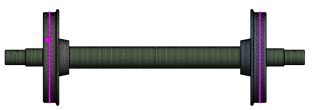
Figure 1. Location of master nodes in the wheel circumference.
2.3. Multibody Dynamic of a Rail Vehicle Model
The vehicle model used for this study is the Addis Ababa Light Rail Transit vehicle that is used to transport passengers in the capital city of Ethiopia. The AALRT vehicle is hinged on three car bodies and has a maximum operating speed of 70 km/h, though the designed speed is 80 km/h.
Each vehicle of AALRT has three cars as shown in Figure 2. The car's body is modeled as a rigid body with mass Mc and moments of inertia Icx, Icy, and Icz along its x, y, and z axes, respectively.
Figure 2. AALRT vehicle-track coupling dynamic model
The vehicle is driven by the motor bogies under car bodies A and C. The car bodies are resting on the secondary springs, which are attached between the bogie and car body. The front and rare motor bogies are connected with a solid normal axle, and the trailer bogie is connected with independently rotating wheels. Double secondary suspension systems are used to attach the motor bogies and the trailing bogies. Between the wheel beam and bogie are attached cylindrical rubber springs that serve as the primary suspension. Standard coil springs and dampers are used for the secondary suspension, and they are mounted between the bogie and the car body . Based on the theory of multi body dynamics (MBD) shown by Eq. (1), locomotive differential equations can be represented as uniform expressions .
Mü+ Cu̇+ Ku = Ft(1)
Where M, C, and K are the locomotive system's mass, damping, and stiffness matrices, respectively, u is the rigid displacement vector, and Ft represents the generalized forces exerted on the locomotive.
The bounce zc and pitch θc represent the carbody vibration modes, while the mass mc and inertia moment Jc show how inert the carbody is in comparison to these modes. The bogies have two degrees of freedom: pitch θbi and bounce zbi, for i = 1 and 2 .
The mass mb and inertia moment Jb are both present in each bogie. Each bogie's secondary suspension's elastic and damping elements are represented using a Kelvin-Voigt system that functions during translation, with the elastic constant 2kzc and the damping constant 2czc. A Kelvin-Voigt system with the elastic constant 2kzb and the damping constant 2czb is used to represent the primary suspension corresponding to an axle during translation. The modelled vehicle is shown in Figure 3.
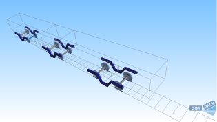
Figure 3. Modeling of car body.
2.4. Wheel-rail Contact Model
The A crucial component of the vehicle-track coupled dynamics model is the wheel-rail contact that connects the vehicle subsystem to the ballastless track subsystem. The wheel-rail contact model assists in studying the geometrical relationship between the wheel and the rail and calculating the amount of contact force on the wheel and rail surface. It is assumed that the wheel and rail have a 0.4 coefficient of friction. According to the Hertzian nonlinear elastic contact theory, the normal and tangential contact forces Fwi (t) between the wheel and rail are computed and expressed as follows :
Zwi(t) represents the vertical displacement of the ith wheelset, Zri (x, t) represents the vertical displacement of the rail at the ith wheelset's location, and CH represents the Hertzian constant, which is equal to 9.37 × 10¹⁰ N/m3/2.
2.5. Coupling the Flexible Wheelset with the Rigid Dynamic Rail Vehicle Model
The FEMBS preprocessing module in SIMPACK reads the substructure analysis output files, which contain the physical and structural data of the wheelset. Applying Eigen mode computations requires the usage of flexible body input files (.fbi), which are produced by FEMBS.
Eigen modes are a flexible structure's natural oscillations. The matching Eigen mode deformation will be triggered when a flexible structure is excited at a frequency that matches one of its Eigen frequencies, as shown in Figure 4.
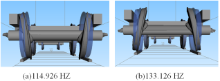
Figure 4. The wheelset Eigen modes at frequencies between 100 and 140Hz.
2.6. Wheel Polygons Mathematical Model
Wheel polygons are classified into two types; periodic and nonperiodic . Periodic discontinuity occurs when a given order polygon dominates; it does not occur when there is no dominance. When the order components of a polygon are widely scattered, it is called nonperiodic discontinuity, and this sort of polygon is generated by the superposition of harmonics with varying amplitudes, wear lengths, and phases. The method of simple harmonic functions is utilized in this research to define the periodic discontinuity of the wheel circumference. The difference in circumferential irregularities is viewed as a harmonic function, as shown by Eq. (2) below.
Δr(β)=Asin(nβ+ β0)r=R-Δr(2)
Where β is the wheel rotation angle, β_0 is the initial phase angle, Δr is the wheel diameter difference, A is the uncircular smooth wear depth, n is the wheel polygon order, R is the nominal rolling circle radius, r is the actual rolling circle radius. The number of orders and degree of polygonal wheel wear are determined by the fixed wavelength principle, which is given by Eq. (3) :
λp=2πrN(3)
Where λp is the wavelength of wheel polygonization, r is the radius of the wheel, and N is the order of the wheel polygonization.
Figure 5 (a-d) shows the 1st, 2nd, 3rd, and 4th-order periodic wheel polygonizations, each with an amplitude of A = 0.1 mm, with the wheel OOR amplitudes enlarged 200 times for ease of inspection. The 1st-order periodic wheel polygonization (N = 1) indicates that the wheel is eccentric because of machining or wear to some extent; this is an issue that all railway wheels experience.
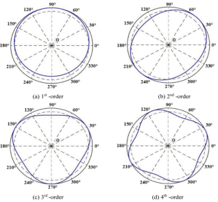
Figure 5. Periodic wheel polygonizations of various orders .
For the 2nd-order periodic polygonization situation (N = 2), the wheel is elliptic, as illustrated in Figure 5 (b), and for the 3rd-order periodic polygonization example (N = 3), it tends to be triangulated. Figure 5 (d) illustrates the wheel's quadrilateral polygonization for N = 4.
2.7. Ride Comfort Index Calculation
For the evaluation and assessment of passenger ride comfort, it is necessary to know the accelerations in individual directions x, y, and z. Therefore, the sensors were defined in the front wheelset of the multibody dynamics system. The indexes were extracted from the results tool of the sensor.
The computation of the passenger ride comfort index at the rail car floor level consists of multiple steps . Procedure outputs are frequency weighted RMS-values of acceleration aXP95Wd, aYP95Wd and aZP95Wb respectively, where a is RMS-values of acceleration X, Y and Z are directions of acceleration, p is measured position, 95 signifies the 95th percentile, Wd is weighted in the x and y directions at the floor level, and Wb is weighted in the z direction at the floor level.
Wz= 6×(aXP95Wd)2+(aYP95Wd)2+(aZP95Wb)2(4)
Eq. (4) was used to calculate the ride indexes, and the scale in Table 2 was used to compare the estimated comfort indexes to the passenger ride comfort according to EN 12299: 2009.
Table 2. Comfort index evaluation scale .

Ride index

Comfortability

Wz < 1.5

Very comfortable

1.5 <Wz < 2.5

Comfortable

2.5 <Wz < 3.5

Medium

3.5<Wz < 4.4

Uncomfortable

Wz > 4.5

Very Uncomfortable

3. Results and Discussion
Six different cases were considered to determining the effect of train speed on ride comfort due to influence of vehicle speed.
Case I: Running a vehicle having a rated carrying load with a polygonized wheel and without a polygonized wheel.
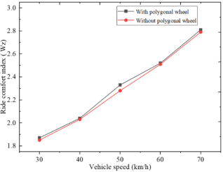
Figure 6. Influence of vehicle speed with rated passenger’s carrying load on ride comfort.
At first, the vehicle with a 59.24-tonne load was run at speeds of 30 km/h, 40 km/h, 50 km/h, 60 km/h, and 70 km/h without a polygonal wheel, and then the same runs were done with a polygonal wheel. Figure 6 shows the ride comfort index versus vehicle speeds. It was observed that ride comfort varies at different speeds. The highest speed (70 km/h) has a greater effect on ride comfort, whether the wheel is polygonized or unpolygonized, as shown in Fig. 6 and summarized in Table 3. With a polygonal wheel, the maximum ride comfort index is 2.81 caused by a speed of 70 km/h and the minimum ride comfort index is 1.86 caused by a speed of 30 km/h, while without a polygonal wheel, the maximum ride comfort index is 2.79 caused by a speed of 70 km/h and the minimum ride comfort index is 1.85 caused by a speed of 30 km/h.
Table 3. Results due to different vehicle speeds and the rated passenger’s carrying load.

Vehicle speed (km/h)

Ride index

With polygonised wheel

Without polygonised wheel

30

1.87

1.85

40

2.04

2.03

50

2.33

2.28

60

2.52

2.51

70

2.81

2.79

Case II: Running a vehicle carrying an overload with a polygonized wheel and without a polygonized wheel.
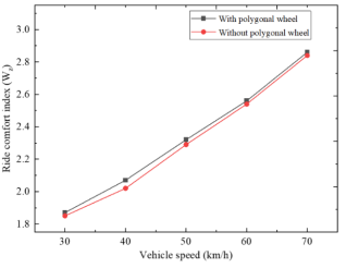
Figure 7. Influence of vehicle speed with overloaded loads on ride comfort.
The vehicle with a 63.02-tonne load was run at speeds of 30 km/h, 40 km/h, 50 km/h, 60 km/h, and 70 km/h without a polygonal wheel, and then the same runs were done with a polygonal wheel. It was observed that ride comfort varies at different speeds. The highest speed (70 km/h) has a greater effect on ride comfort, whether the wheel is polygonized or unpolygonized, as shown in Figure 7 and tabulated in Table 4 With a polygonal wheel, the maximum ride comfort index is 2.83 caused by a speed of 70 km/h and the minimum ride comfort index is 1.87 caused by a speed of 30 km/h, while without a polygonal wheel, the maximum ride comfort index is 2.84 caused by a speed of 70 km/h and the minimum ride comfort index is 1.85 caused by a speed of 30 km/h.
Table 4. Results due to different vehicle speeds with overloaded passenger carrying capacity.

Vehicle speed (km/h)

Ride index

With polygonised wheel

Without polygonised wheel

30

1.87

1.85

40

2.07

2.03

50

2.32

2.29

60

2.55

2.54

70

2.86

2.84

Case III: Running a vehicle with a rated carrying load with two polygonized wheels from different bogies.
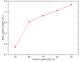
Figure 8. Ride comfort index due to vehicle speed with a rated passenger’s carrying load and two polygonized wheels.
The vehicle with a 59.24-tonne load was run at speeds of 30 km/h, 40 km/h, 50 km/h, 60 km/h, and 70 km/h with polygonized wheels on the first and second bogies. Figure 8 shows the ride comfort index versus vehicle speeds. It was observed that ride comfort varies at different speeds. The highest speed (70 km/h) has a greater effect on ride comfort; see Table 5. The maximum ride comfort index is 2.86 at a speed of 70 km/h, and the minimum ride comfort index is 1.87 at a speed of 30 km/h.
Table 5. Ride comfort index due to vehicle speed with a rated passenger’s carrying load and two polygonized wheels.

Vehicle speed (km/h)

Ride comfort index

30

1.86

40

2.04

50

2.32

60

2.56

70

2.84

Case IV: Running a vehicle carrying an overload with two polygonized wheels from different bogies.
The vehicle with a 63.02-tonne load was run at speeds of 30 km/h, 40 km/h, 50 km/h, 60 km/h, and 70 km/h with polygonized wheels on the first and second bogies. Figure 9 shows the ride comfort index versus vehicle speeds. It was observed that ride comfort varies at different speeds. The highest speed (70 km/h) has a greater effect on ride comfort; see Table 6. The maximum ride comfort index is 2.87 at a speed of 70 km/h, and the minimum ride comfort index is 1.87 at a speed of 30 km/h.
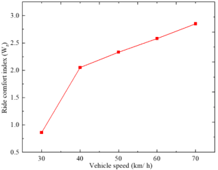
Figure 9. Ride comfort index due to vehicle speed with overload passenger’s carrying load and two polygonized wheels.
Table 6. Ride comfort index due to vehicle speed with overload passenger’s carrying load and two polygonized wheels.

Vehicle speed (km/h)

Ride comfort index

30

1.86

40

2.05

50

2.34

60

2.58

70

2.85

Case V: Running a vehicle with a rated carrying load with three polygonized wheels from different bogies.
The vehicle with a 59.24-tonne load was run at speeds of 30 km/h, 40 km/h, 50 km/h, 60 km/h, and 70 km/h with one polygonized wheel on each bogie. Figure 10 shows the ride comfort index versus vehicle speeds. It was observed that ride comfort varies at different speeds. The highest speed (70 km/h) has a greater effect on ride comfort; see Table 7. The maximum ride comfort index is 2.86 at a speed of 70 km/h, and the minimum ride comfort index is 1.88 at a speed of 30 km/h.
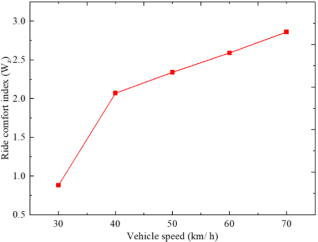
Figure 10. Ride comfort index due to vehicle speed with a rated passenger’s carrying load and three polygonized wheels.
Table 7. Ride comfort index due to vehicle speed with a rated passenger’s carrying load and three polygonized wheels.

Vehicle speed (km/h)

Ride comfort index

30

1.86

40

2.07

50

2.34

60

2.59

70

2.86

Case VI: Running a vehicle carrying an overload with three polygonized wheels from different bogies
The vehicle with a 63.02-tonne load was run at speeds of 30 km/h, 40 km/h, 50 km/h, 60 km/h, and 70 km/h with one polygonized wheel on each bogie. Figure 11 shows the ride comfort index versus vehicle speeds. It was observed that ride comfort varies at different speeds. The highest speed (70 km/h) has a greater effect on ride comfort; see Table 8. The maximum ride comfort index is 2.87 at a speed of 70 km/h, and the minimum ride comfort index is 1.87 at a speed of 30 km/h.
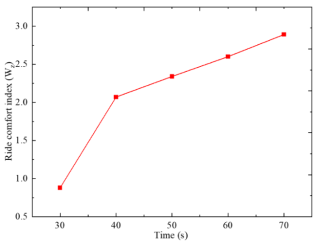
Figure 11. Ride comfort index due to vehicle speed with overload passenger’s carrying load and three polygonized wheels.
Table 8. Ride comfort index due to vehicle speed with overload passenger’s carrying load and three polygonized wheels.

Vehicle speed (km/h)

Ride comfort index

30

1.88

40

2.07

50

2.34

60

2.6

70

2.89

The results have also been proved by published works . Therefore, operation at a high speed of 70 km/h will reduce the comfort of passengers. Refer to Table 2 for the ride comfort index evaluation scale.
4. Conclusions
The following conclusions were drawn upon completion of the study:
1) With increasing vehicle speed, the ride index also increases, which means that at high speeds, the ride comfort being diminished.
2) Oders of wheel polygonization also found that they have an effect on ride comfort. With the increasing order of polygonization, the ride index also increases.
3) Running a vehicle carrying an overload with three polygonized wheels from different bogies has more negative effect on passenger ride comfort comparing to the running a vehicle with a rated carrying load with two polygonized wheels from different bogies.
4) The results show that this study significantly affects both operation management and wheel and rail maintenance planning. However, more research should be done on the impact on passenger comfort of operating a railway vehicle with a high order of wheel polygonization and one with all wheels polygonized.
Abbreviations

OOR

Out of Roundness

FEM

Finite Element Method

AALRT

Addis Ababa Light Rail Transit

MBD

Multi Body Dynamics

YTS

Yield Stress

UTS

Ultimate Stress

ISO

International Organization for Standardization

EN

European Technical Standards

ABDL

Ansys Parametric Design Language

FEMBS

Finite Element Multi Body Systems

FE

Finite Element

ANSYS

Analysis System

Author Contributions
Mazuri Erasto Lutema: Conceptualization, Data curation, Investigation, Methodology, Resources, Software, Validation, Writing original draft, Writing review & editing
Haileleoul Sahle Habte: Methodology, Supervision, Writing review & editing
Tindiwensi Edison: Software, Validation, Writing original draft, Writing review & editing
Funding
This work is not supported by any external funding.
Data Availability Statement
The data is available from the corresponding author upon reasonable request.
Conflicts of Interest
The authors declare no conflicts of interest.
References
[1] Y. Peng et al., “A review of passenger ride comfort in railway: assessment and improvement method,” Transp. Saf. Environ., Vol. 4, No. 2, pp. 1-16, (2022),
[2] M. Loulová, A. Suchánek, and J. Harušinec, “Evaluation of the Parameters Affecting Passenger Riding Comfort of a Rail Vehicle,” Manuf. Technol., Vol. 17, No. 2, pp. 224-231, (2017), [Online]. Available:
[3] G. Wang, C. Xie, J. H. Park, W. H. Kim, and C. Soo, “Critical points numerical analysis of ride comfort of the flexible railway carbody Critical points numerical analysis of ride comfort of the flexible railway carbody,” Vol. 24, No. 7, pp. 24-31, (2019),
[4] L. Jing, K. Wang, and W. Zhai, “Impact vibration behavior of railway vehicles: a state-of-the-art overview,” Acta Mech. Sin. Xuebao, Vol. 37, No. 8, pp. 1193-1221, (2021),
[5] J. Dižo, M. Blatnický, S. Steišunas, and B. Skočilasová, “Assessment of a rail vehicle running with the damaged wheel on a ride comfort for passengers,” MATEC Web Conf., Vol. 157, pp. 1-11, (2018),
[6] A. Guizani, M. Hammadi, J. Choley, T. Soriano, M. S. Abbes, and M. Haddar, “Multiphysics Modelling and Simulation for Systems Design and Monitoring,” Multiphysics Model. Simul. Syst. Des. Monit., pp. 189-198, (2015),
[7] Suchánek, M. Loulová, and J. Harušinec, “Evaluation of passenger riding comfort of a rail vehicle by means dynamic simulations,” MATEC Web Conf., Vol. 254, p. 03009, (2019),
[8] G. Wang, C. Xie, J. H. Park, W. H. Kim, and C. Soo, “Ride comfort enhancement in railway vehicle by the reduction of the car body structural flexural vibration Ride comfort enhancement in railway vehicle by the reduction of the car body structural flexural vibration,” Vol. 41, No. 32, pp. 14-23, (2017),
[9] J. Dižo et al., “Evaluation of ride comfort in a railway passenger car depending on a change of suspension parameters,” Sensors, Vol. 21, No. 23, pp. 22-30, (2021),
[10] Y. Ye, D. Shi, P. Krause, Q. Tian, and M. Hecht, “Wheel flat can cause or exacerbate wheel polygonization,” Veh. Syst. Dyn., Vol. 58, No. 10, pp. 1575-1604, (2020),
[11] U. Olofsson and K. Sundvall, “Influence of leaf, humidity and applied lubrication on friction in the wheel-rail contact: Pin-on-disc experiments,” Proc. Inst. Mech. Eng. Part F J. Rail Rapid Transit, Vol. 218, No. 3, pp. 235-242, (2004),
[12] D. W. Barke and W. K. Chiu, “A review of the effects of out-of-round wheels on track and vehicle components,” Proc. Inst. Mech. Eng. Part F J. Rail Rapid Transit, Vol. 219, No. 3, pp. 151-175, (2005),
[13] Peng, S. Iwnicki, P. Shackleton, and Y. Song, “General conditions for railway wheel polygonal wear to evolve,” Veh. Syst. Dyn., Vol. 59, No. 4, pp. 568-587, (2021),
[14] M. Dumitriu and M. A. Gheti, “Evaluation of the ride quality and ride comfort in railway annals of Faculty Engineering Hunedoara - International Journal of Engineering, no. January, Vol. 21, No. 3, pp. 34-41, (2016).
[15] M. Dumitriu, “Numerical analysis on the influence of suspended equipment on the ride comfort in railway vehicles,” Arch. Mech. Eng., Vol. 65, No. 4, pp. 477-496, (2018),
[16] A. Momhur, Y. X. Zhao, W. Q. Li, Y. Z. Sun, and X. L. Zou, “Flexible-Rigid Wheelset Introduced Dynamic Effects due to Wheel Tread Flat,” Shock Vib., Vol. 6, 2021, pp. 13-23, (2021),
[17] J. Wu and Y. Qiu, “Modelling and ride comfort analysis of a coupled track-train-seat-human model with lateral, vertical and roll vibrations,” Vol. 13, No. 15, May, pp. 24-34, (2021),
[18] J. Dižo, M. Blatnický, and R. Melnik, “Assessment of the Passenger Ride Comfort for a Coach by Means of Simulation Computations,” Vol. 8, No. 2, pp. 24-32, 2017,
[19] J. Dižo, M. Blatnický, S. Steišūnas, and G. Vaičiūnas, “Evaluation of the Influence of a Rail Vehicle Running with Wheel-flat on the Railway Track,” Vol. 9, No. 1, pp. 24-31, (2018),
[20] E. Kardas-cinal, “Analysis of ride comfort in selected types of rail vehicles Analiza komfortu jazdy pasażera wybranych typów pojazdów szynowych,” Vol. 51, No. 4, pp. 157-183, (2021),
[21] G. Wang, C. Xie, Q. Zhou, and P. Yuan, “Experimental Analysis of Ride Comfort Quality for High-speed Railway Vehicles Experimental Analysis of Ride Comfort Quality for High-speed Railway Vehicles,” Vol. 3, No. 7, pp. 12-23, (2020),
[22] Y. Zeng, D. Song, and W. Zhang, “Risk assessment of wheel polygonization on high-speed trains based on Bayesian networks,” Vol. 10, No. 45, pp. 1-11, (2020),
[23] M. Dumitriu and D. I. Stănică, “Study on the evaluation methods of the vertical ride comfort of railway vehicle—mean comfort method and sperling’s method,” Appl. Sci., Vol. 11, No. 9, pp. 86-99, (2021),
[24] V. Kumar, V. Rastogi, and P. M. Pathak, “Simulation for whole-body vibration to assess ride comfort of a low-medium speed railway vehicle,” Simulation, Vol. 93, No. 3, pp. 225-236, (2017),
[25] Z. Chen and G. Zhu, “Dynamic evaluation on ride comfort of metro vehicle considering structural flexibility,” Arch. Civ. Mech. Eng., Vol. 21, No. 4, pp. 1-16, (2021),
[26] G. Tao, M. Liu, Q. Xie, and Z. Wen, “Wheel-rail dynamic interaction caused by wheel out-of-roundness and its transmission between wheelsets,” Proc. Inst. Mech. Eng. Part F J. Rail Rapid Transit, Vol. 236, No. 3, pp. 247-261, (2022),
[27] G. Bethel Lulu, R. Chen, P. Wang, J. Xu, J. Chen, and J. Fang, “Random vibration analysis of tram-track interaction on a curve due to the polygonal wheel and track irregularity,” Veh. Syst. Dyn., Vol. 60, No. 4, pp. 1125-1147, (2022),
[28] Y. Yang, L. Ling, Y. Yang, S. Chen, and K. Wang, “Effects of wheelset flexibility on locomotive-track interaction due to rail weld irregularities,” Veh. Syst. Dyn., Vol. 60, No. 9, pp. 3088-3108, (2022),
[29] M. Dumitriu, “Numerical study of the inuence of suspended equipment on ride comfort in high-speed railway vehicles,” Sci. Iran., Vol. 27, No. 4 B, pp. 1897-1915, (2020),
[30] J. N. Costa, J. Ambrósio, D. Frey, and A. R. Andrade, “A multivariate statistical representation of railway track irregularities using ARMA models,” Veh. Syst. Dyn., vol. 60, no. 7, pp. 2494-2510, (2022),
[31] Y. Dai and C. Ye, “Influence of Wheel Polygons on Dynamic Performance of Trains,” Vol. 5, No. 2, pp. 44-61, (2023).
[32] L. Jing, Z. Liu, and K. Liu, “A mathematically-based study of the random wheel-rail contact irregularity by wheel out-of-roundness,” Veh. Syst. Dyn., Vol. 60, No. 1, pp. 335-370, (2022),
[33] Baeza L, Fayos J, Roda A, “High frequency railway vehicle-track dynamics through flexible rotating wheelsets,” Veh. Syst. Dyn., Vol. 46, No. 7, pp. 647-659, (2008),
[34] Fu, S. Bruni, and S. Luo, “Study on wheel polygonization of a metro vehicle based on polygonal wear simulation,” Wear, Vol. 438, No. 10, p. 203071, (2019),
Cite This Article
  • APA Style

    Lutema, M. E., Habte, H. S., Edison, T. (2025). Dynamic Analysis of the Influence of Railway Vehicle Speed on Passenger Ride Comfort When Wheels Undergo Polygonization Defects. International Journal of Mechanical Engineering and Applications, 13(2), 53-62. https://doi.org/10.11648/j.ijmea.20251302.11

    Copy | Download

    ACS Style

    Lutema, M. E.; Habte, H. S.; Edison, T. Dynamic Analysis of the Influence of Railway Vehicle Speed on Passenger Ride Comfort When Wheels Undergo Polygonization Defects. Int. J. Mech. Eng. Appl. 2025, 13(2), 53-62. doi: 10.11648/j.ijmea.20251302.11

    Copy | Download

    AMA Style

    Lutema ME, Habte HS, Edison T. Dynamic Analysis of the Influence of Railway Vehicle Speed on Passenger Ride Comfort When Wheels Undergo Polygonization Defects. Int J Mech Eng Appl. 2025;13(2):53-62. doi: 10.11648/j.ijmea.20251302.11

    Copy | Download

  • @article{10.11648/j.ijmea.20251302.11,
      author = {Mazuri Erasto Lutema and Haileleoul Sahle Habte and Tindiwensi Edison},
      title = {Dynamic Analysis of the Influence of Railway Vehicle Speed on Passenger Ride Comfort When Wheels Undergo Polygonization Defects
    },
      journal = {International Journal of Mechanical Engineering and Applications},
      volume = {13},
      number = {2},
      pages = {53-62},
      doi = {10.11648/j.ijmea.20251302.11},
      url = {https://doi.org/10.11648/j.ijmea.20251302.11},
      eprint = {https://article.sciencepublishinggroup.com/pdf/10.11648.j.ijmea.20251302.11},
      abstract = {The railway transportation system is currently undergoing a significant expansion. As a result, train lines are upgraded, and the technical condition of the rail vehicles that use them is also taken into consideration. However, under certain circumstances, wheels on rail vehicles may sustain damage while in use. Then, depending on the kind and degree of flaws, the profile of the wheels is no longer circular but rather changes. The quality of a passenger's ride comfort is diminished when a rail vehicle with a damaged wheel is in operation. The research considered one type of railway wheel untrueness wheel polygonization and focused on the evaluation of ride comfort for passengers based on results obtained from numerical and dynamic analyses. Simulations and calculations were carried out in numerical and dynamic multibody software. The results show that with increasing vehicle speed, the ride index also increases, which means that at high speeds, the ride comfort will be diminished. Furthermore, it found that the orders of wheel polygonization have an effect on ride comfort. With the increasing order of polygonization, the ride index also increases. According to the findings, this study has a significant impact on the maintenance planning for wheels and rails as well as operation management.
    },
     year = {2025}
    }
    

    Copy | Download

  • TY  - JOUR
    T1  - Dynamic Analysis of the Influence of Railway Vehicle Speed on Passenger Ride Comfort When Wheels Undergo Polygonization Defects
    
    AU  - Mazuri Erasto Lutema
    AU  - Haileleoul Sahle Habte
    AU  - Tindiwensi Edison
    Y1  - 2025/03/07
    PY  - 2025
    N1  - https://doi.org/10.11648/j.ijmea.20251302.11
    DO  - 10.11648/j.ijmea.20251302.11
    T2  - International Journal of Mechanical Engineering and Applications
    JF  - International Journal of Mechanical Engineering and Applications
    JO  - International Journal of Mechanical Engineering and Applications
    SP  - 53
    EP  - 62
    PB  - Science Publishing Group
    SN  - 2330-0248
    UR  - https://doi.org/10.11648/j.ijmea.20251302.11
    AB  - The railway transportation system is currently undergoing a significant expansion. As a result, train lines are upgraded, and the technical condition of the rail vehicles that use them is also taken into consideration. However, under certain circumstances, wheels on rail vehicles may sustain damage while in use. Then, depending on the kind and degree of flaws, the profile of the wheels is no longer circular but rather changes. The quality of a passenger's ride comfort is diminished when a rail vehicle with a damaged wheel is in operation. The research considered one type of railway wheel untrueness wheel polygonization and focused on the evaluation of ride comfort for passengers based on results obtained from numerical and dynamic analyses. Simulations and calculations were carried out in numerical and dynamic multibody software. The results show that with increasing vehicle speed, the ride index also increases, which means that at high speeds, the ride comfort will be diminished. Furthermore, it found that the orders of wheel polygonization have an effect on ride comfort. With the increasing order of polygonization, the ride index also increases. According to the findings, this study has a significant impact on the maintenance planning for wheels and rails as well as operation management.
    
    VL  - 13
    IS  - 2
    ER  - 

    Copy | Download

Author Information
  • Department of Automotive and Mechanical Engineering, National Institute of Transport, Dar es Salaam, Tanzania

    Biography: Mazuri Erasto Lutema is a professional mechanical engineer and has been an assistant lecturer in the faculty of transport engineering and technology at the National Institute of Transport since 2020. He completed his MSc at Addis Ababa University, where he majored in railway engineering, and his undergraduate studies at the National Institute of Transport, where he majored in mechanical engineering. His research interests lie in the areas of vehicle system dynamics, railway vehicle design, and wheel-rail interaction, ranging from theory to design to im-plementation. He has published two papers in highly selective journals in the mechanical engineering field.

    Research Fields: Vehicle system dynamics, railway vehicle design, wheel-rail interaction and mechanics of materials.

  • School of Industrial and Mechanical Engineering, Addis Ababa University, Addis Ababa, Ethiopia

    Research Fields: Finite element method, thermos design, mechanics of materials, plastic deformation, energy absorbing structures.

  • School of Engineering and Applied Sciences, Kampala International University, Kampala, Uganda

    Biography: Tindiwensi Edison is a mechanical and railway engineer with demonstrated knowledge in automobiles, machine tools, electrical machines as well as railways (wheel/rail interaction, rail motive power, Railway Safety Risk Management Rail-Vehicle System Dynamics, rail vehicle design, and rolling stock construction and maintenance). Skilled in Finite Element Analysis, Fatigue Analysis, Computer-Aided Design, and Research work. Proficient in carefully diagnosing and assessing mechanical faults and rendering real suitable solutions. Passionate about hardworking, very interactive, thoughtful, and open-minded person, who strives to utilize acquired knowledge and expertise for excellent engineering results.

    Research Fields: Rail-Vehicle System Dynamics, rail vehicle design, and Fatigue Analysis.